Top 10 Ways to Troubleshoot Heat Pump Flow Switch Errors?

Time:2026-10-07 Author:Ethan
0%

A heat pump flow switch error can appear suddenly, often when the unit runs but produces little heating or cooling. The display may show a warning, while the circulation pump hums beside a lukewarm pipe. Understanding how to troubleshoot a heat pump flow switch error requires more than resetting the controller. It requires careful observation, safe testing, and respect for the system’s hydraulic design.

John Siegenthaler, P.E., a respected hydronic-heating engineer, offers a useful diagnostic principle: “Follow the evidence, not the assumption.” That advice matters here. A flow switch may be reacting correctly to weak circulation, trapped air, a blocked filter, a closed valve, low water pressure, or a failed sensor. The switch itself is not always the true fault.

Start with the simple clues. Check the filter. Inspect the valves. Listen for air. Confirm pump operation. Then compare actual flow conditions with the manufacturer’s specifications. Never bypass the switch as a permanent solution. That shortcut can hide a freeze-protection problem or damage the compressor.

Small details matter.

This guide presents ten practical troubleshooting methods for technicians, homeowners, and maintenance teams. It also recognizes an uncomfortable reality: not every error has one obvious cause. Wiring may look correct but fail under vibration. A clean filter may still conceal a weak pump. Careful testing is slower than guessing, yet it prevents repeated shutdowns, unnecessary part replacement, and expensive system damage. Safety comes first, especially around electrical terminals, pressurized water, and moving components.
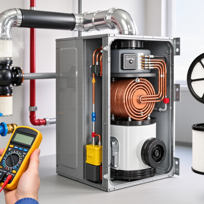
Top 10 Ways to Troubleshoot Heat Pump Flow Switch Errors?

Define the Flow-Switch Fault and Compare Flow with 2–3 GPM per Ton

A heat-pump flow-switch error means the control circuit does not confirm enough water movement. The switch may be open, even when the pump is running. Air pockets, a dirty strainer, closed valves, wiring faults, or a failing sensor can cause this condition. Do not replace the switch immediately. Measure actual flow first.

For hydronic and geothermal systems, 2–3 gallons per minute per ton is a useful field benchmark. A three-ton unit may therefore need roughly 6–9 GPM. ASHRAE Handbook—HVAC Systems and Equipment identifies water flow as a critical design factor for heat-transfer performance. IGSHPA installation guidance also uses tonnage-based flow calculations for ground-loop systems. These figures are not universal. Manufacturer data, pipe length, antifreeze concentration, and entering-water temperature can change the requirement.

Check the pump, pressure difference, valve position, strainer, and flow meter. Then compare the reading with the equipment’s commissioning sheet. A 3-ton system showing only 3 GPM is not “close enough”; it is operating near 1 GPM per ton. That can trigger nuisance faults, unstable leaving-water temperatures, and compressor protection. The reverse problem matters too. Excessive flow can increase pump energy without producing useful capacity. Field technicians sometimes trust a pump’s nameplate and skip measurement. That shortcut deserves review. A switch error is often a symptom, not the root cause.

Check Pumps, Valves, Strainers, and Air Using Pressure and Delta-T Data

When a heat pump reports a flow switch error, do not replace the switch immediately. Confirm power is isolated before opening the panel. Check whether the circulation pump starts, hums, or trips its protection. A silent pump may indicate a control, wiring, or motor problem. Verify that isolation valves are fully open, including valves near the indoor coil.

Pressure readings can reveal restrictions. Measure pressure before and after the strainer, pump, and heat exchanger. A large pressure drop across the strainer often indicates trapped dirt. Clean it carefully, then retest the system. Low pump differential pressure may point to a closed valve, worn impeller, or air-bound circuit. A pressure gauge alone can mislead.

Use supply and return temperatures to confirm actual heat transfer. A high delta-T often suggests low flow, while an unusually small delta-T may indicate excessive flow or weak heat exchange. Compare readings with the equipment’s specified operating range, not a guessed number. Bleed air from high points and listen for gurgling near the pump. I have seen a flow switch reset after air removal, but that result should not end the investigation. Recheck pressure, delta-T, and switch continuity under operating conditions. If readings remain abnormal, inspect the switch wiring and sensor position with calibrated instruments. An intermittent error deserves attention, even when the system temporarily runs.

Test Switch Continuity, Wiring, and the Common 24 VAC Control Circuit

Top 10 Ways to Troubleshoot Heat Pump Flow Switch Errors

A flow switch error often begins with insufficient water movement, not a failed switch. Turn off power, inspect the filter, and confirm the pump runs without unusual noise. Check valves, strainers, and air pockets near the heat exchanger. A blocked circuit can leave the switch open, even when the thermostat calls for heating. The U.S. Department of Energy reports that properly installed heat pumps can deliver roughly 1.5 to 3 times more heat energy than the electrical energy they consume. That efficiency depends on stable flow and accurate controls.

Test the switch continuity with power isolated. The contacts should change state when flow reaches the manufacturer’s specified threshold. Do not guess. Use a calibrated meter and record the result. Inspect every wire for loose terminals, corrosion, damaged insulation, or a pinched section. Trace the common 24 VAC control circuit from the transformer to the thermostat, flow switch, safety controls, and relay coil. Measure voltage between R and C, then check voltage across the switch during a call. A missing 24 VAC signal may indicate an open fuse, failed transformer, broken common wire, or miswired safety circuit.

Keep hands clear of moving equipment. Pressure matters. So does timing. Some switches need several seconds before closing. ACCA quality-installation guidance emphasizes verifying electrical connections, airflow, and operating conditions rather than replacing parts blindly. I have seen technicians overlook a simple air lock. Recheck the wiring diagram, reset the system, and confirm that the switch opens when flow stops. Local conditions can mislead the first test.

Verify Flow-Switch Settings Against Manufacturer Delay and Pressure Ratings

A flow-switch error often points to incorrect timing or pressure settings, not a failed switch. In field troubleshooting, I check the manufacturer’s delay period before replacing parts. Some systems need several seconds to confirm stable water movement. A pump may run normally while the switch remains open briefly. That delay can trigger a false alarm.

Compare the installed settings with the equipment manual and the switch’s pressure rating. Check the cut-in and cut-out values carefully. Never adjust beyond the listed limits. Excessive pressure can damage components or create unsafe operating conditions. Inspect the filter, strainer, and valves for restriction. Even a small blockage can reduce flow below the switch threshold. Record the pressure before and after cleaning. This evidence helps separate a flow problem from a calibration problem. My own judgment can be wrong here, especially when gauges are poorly placed or unverified.

Tips: Turn off power before opening the control panel. Confirm the pump is primed and all valves are open. Test the switch with a calibrated gauge, not guesswork. Watch the delay timer during startup. If the error disappears only after repeated resets, stop resetting it and investigate the cause. A temporary fix can hide a weak pump or an incorrect pressure setting.

Top 10 Ways to Troubleshoot Heat Pump Flow Switch Errors

Verify Flow-Switch Settings Against Manufacturer Delay and Pressure Ratings

The chart shows practical reference values commonly checked during heat-pump flow-switch troubleshooting. Confirm the exact delay, differential-pressure requirement, contact rating, and reset behavior against the equipment manufacturer’s documentation before making adjustments. A switch that proves too slowly may indicate restricted flow, trapped air, a dirty strainer, incorrect pump operation, or an unsuitable pressure setting.

Confirm Repairs Through Stable Flow, 8–12°F Delta-T, and Error-Free Cycling

A heat pump flow-switch error needs measured proof, not a quick reset. After cleaning strainers and checking valves, record supply and return temperatures under steady load. A stable 8–12°F Delta-T often indicates acceptable water-side heat transfer, but always compare it with the equipment’s design data. A reading near 2°F may suggest excessive flow or weak heat exchange. A reading above 15°F can indicate restricted flow, air, or a partially closed valve. Conditions matter.

Watch the pressure gauge, pump sound, and flow indication together. The system should run without surging, rattling, or repeated switch trips. Let it complete several heating and defrost cycles. One successful start proves little. The U.S. Department of Energy reports that properly installed air-source heat pumps can deliver two to four units of heat for each unit of electricity consumed. Poor flow can quickly undermine that efficiency. ENERGY STAR also reports potential heating-electricity savings of about 50% when replacing electric resistance heating with a qualified heat pump.

Record outdoor temperature, entering-water temperature, leaving-water temperature, and fault history. Then repeat the test after the system reaches operating temperature. I have seen technicians trust a single Delta-T reading, and that shortcut caused a return visit. A stable reading is better evidence. Still, the 8–12°F range is a field checkpoint, not a universal rule. Confirm the repair only when flow remains steady, Delta-T stays consistent, and the control completes multiple error-free cycles.

FAQS

What does a heat-pump flow-switch fault mean?

The control circuit does not confirm enough water movement. The switch may stay open while the pump runs. Air pockets, blocked strainers, closed valves, wiring faults, or sensor failure can cause it. A fault is often a symptom, not the root cause.

How much water flow does a heat-pump system usually need?

A practical field benchmark is 2–3 gallons per minute per ton. A three-ton unit may need about 6–9 GPM. These figures are not universal. Pipe length, antifreeze concentration, water temperature, and equipment data can change the requirement.

Why is 3 GPM too low for a three-ton system?

It provides only about 1 GPM per ton. That may cause nuisance faults and unstable leaving-water temperatures. Compressor protection may also activate. “Close enough” is not a safe assumption.

What should be checked before replacing the flow switch?

Check the pump, pressure difference, valve positions, strainer, air pockets, and flow-meter reading. Compare actual flow with the commissioning sheet. Inspect the pump for unusual noise. A pump nameplate does not prove real system flow.

How can I test flow-switch continuity safely?

Turn off and isolate electrical power before testing. Use a calibrated meter across the switch contacts. The contacts should change state at the specified flow threshold. Do not guess.

What wiring checks help diagnose a flow-switch error?

Inspect terminals for looseness, corrosion, damaged insulation, or pinched wires. Trace the common 24 VAC circuit through the transformer, thermostat, safety controls, switch, and relay. Measure voltage between R and C. Then measure voltage across the switch during a heating call.

Why might the flow switch need several seconds to close?

Some switches require a delay before confirming stable movement. The pump may start normally, while the switch remains open briefly. Check the listed delay period and observe startup timing. Repeated resets can hide the real problem.

How do pressure settings affect flow-switch operation?

Compare cut-in and cut-out values with the equipment instructions. Check the switch pressure rating carefully. Never adjust beyond listed limits. A blocked filter can reduce pressure and flow below the switching threshold.

What practical details should technicians record during troubleshooting?

Record flow, pressure before cleaning, pressure after cleaning, voltage readings, and switch timing. Confirm the pump is primed and valves are open. I can misjudge a diagnosis when gauges are poorly placed. Recheck the wiring diagram.

Conclusion

How to troubleshoot a heat pump flow switch error? Start by defining the fault and confirming that the system is receiving adequate water flow, typically around 2–3 GPM per ton of capacity. Inspect the circulation pumps, isolation valves, strainers, and piping for blockages, closed valves, or trapped air. Pressure readings and supply-to-return temperature differences can help identify restricted or insufficient flow.

Next, test the flow switch for continuity and examine its wiring, terminals, and common 24 VAC control circuit for loose connections or interruptions. Check that the switch setting matches the system’s required pressure range and manufacturer-specified delay. After correcting any problems, run the heat pump through several heating and cooling cycles. Stable pressure, an 8–12°F delta-T, consistent flow, and error-free cycling indicate that the repair has been successful. If the fault returns, reassess the hydraulic circuit and control signals before replacing components.

Ethan

Ethan

Ethan is a seasoned marketing professional with a deep expertise in our company's innovative product line. With a passion for sharing knowledge and insights, he takes the lead in regularly updating our corporate blog, where he explores industry trends, product features, and effective marketing......